
Page 115 - Introduction to Microcontrollers Architecture, Programming, and Interfacing of The Motorola 68HC12
P. 115
92 Chapter 4 Assembly Language Programming
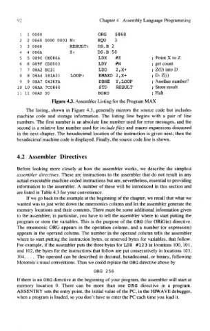
1 1 0000 ORG $868
2 2 0868 0000 0003 N: EQU 3
3 3 0868 RESULT: DS.B 2
4 4 086A Z: DS.B 50
5 5 089C CE086A LDX #Z ; Point X to Z
6 6 089F CD0003 LDY #N ; get count
7 7 08A2 EC31 LDD 2,X+ ; Z(0) into D
8 8 08A4 181A31 LOOP: EMAXD 2,X+ ; D- Z(i)
9 9 08A7 0436FA DBNE Y,LOOP ; Another number?
10 10 08AA 7C0868 STD RESULT ; Store result
11 11 08AD 00 BGND ; Halt
Figure 43. Assembler Listing for the Program MAX
The listing, shown in Figure 4.3, generally mirrors the source code but includes
machine code and storage information. The listing line begins with a pair of line
numbers. The first number is an absolute line number used for error messages, and the
second is a relative line number used for include files and macro expansions discussed
in the next chapter. The hexadecimal location of the instruction is given next; then the
hexadecimal machine code is displayed. Finally, the source code line is shown.
4.2 Assembler Directives
Before looking more closely at how the assembler works, we describe the simplest
assembler directives. These are instructions to the assembler that do not result in any
actual executable machine coded instructions but are, nevertheless, essential to providing
information to the assembler. A number of these will be introduced in this section and
are listed in Table 4.3 for your convenience.
If we go back to the example at the beginning of the chapter, we recall that what we
wanted was to just write down the mnemonics column and let the assembler generate the
memory locations and their contents. There must be some additional information given
to the assembler; in particular, you have to tell the assembler where to start putting the
program or store the variables. This is the purpose of the ORG (for ORiGin) directive.
The mnemonic ORG appears in the operation column, and a number (or expression)
appears in the operand column. The number in the operand column tells the assembler
where to start putting the instruction bytes, or reserved bytes for variables, that follow.
For example, if the assembler puts the three bytes for LDX #123 in locations 100,101,
and 102, the bytes for the instructions that follow are put consecutively in locations 103,
104, . . .. The operand can be described in decimal, hexadecimal, or binary, following
Motorola's usual conventions. Thus we could replace the ORG directive above by
ORG 256
If there is no ORG directive at the beginning of your program, the assembler will start at
memory location 0. There can be more than one ORG directive in a program.
ABSENTRY sets the entry point, the initial value of the PC, in the HIWAVE debugger,
when a program is loaded, so you don't have to enter the PC each time you load it.