
Page 119 - Introduction to Microcontrollers Architecture, Programming, and Interfacing of The Motorola 68HC12
P. 119
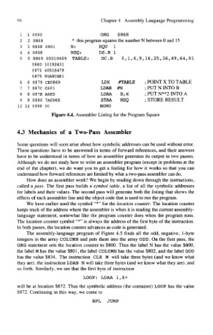
96                                Chapter 4 Assembly Language Programming


          1 1 0000                        ORG $868
          2 2 0868             * this program squares the number N between 0 and 15
          3 3 0868 0001       N:          EQU   I
          4 4 0868            NSQ:        DS.B 1
          5 5 0869 00010409 TABLE:        DC.B     0,1,4,9,16,25,36,49,64,81
               086D 10192431
               0871 40516479
               0875 90A9C4E1
          6 6 0879 CE0869                  LDX   #TABLE     ; POINT X TO TABLE
          7 7 087C C601                   LDAB #N           ; PUT N INTO B
          8 8 087E A6E5                   LDAA    B,X       ; PUT N**2 INTO A
          9 9 0880 7AO868                 STAA    NSQ       ; STORE RESULT
         12 12 088F 00                    BOND
                      Figure 4.4. Assembler Listing for the Program Square


        4.3 Mechanics of a Two-Pass Assembler

         Some questions will soon arise about how symbolic addresses can be used without error.
        These questions have to be answered in terms of forward references, and their answers
        have to be understood in terms of how an assembler generates its output in two passes.
         Although we do not study how to write an assembler program (except in problems at the
        end of the chapter), we do want you to get a feeling for how it works so that you can
        understand how forward references are limited by what a two-pass assembler can do.
            How does an assembler work? We begin by reading down through the instructions,
        called a pass. The first pass builds a symbol table, a list of all the symbolic addresses
         for labels and their values. The second pass will generate both the listing that shows the
        effects of each assembler line and the object code that is used to run the program.
            We have earlier used the symbol "*" for the location counter. The location counter
        keeps track of the address where the assembler is when it is reading the current assembly-
         language statement, somewhat like the program counter does when the program runs.
        The location counter symbol "*" is always the address of the first byte of the instruction.
         In both passes, the location counter advances as code is generated.
            The assembly-language program of Figure 4.5 finds all the odd, negative, 1-byte
         integers in the array COLUMN and puts them into the array ODD. On the first pass, the
         ORG statement sets the location counter to $800. Thus the label N has the value $800,
        the label M has the value $801, the label COLUMN has the value $802, and the label ODD
         has the value $834. The instruction CLR M will take three bytes (and we know what
        they are), the instruction LDAB N will take three bytes (and we know what they are), and
         so forth. Similarly, we see that the first byte of instruction
                                   LOOP: LDAA 1,X+
         will be at location $872. Thus the symbolic address (the container) LOOP has the value
        $872. Continuing in this way, we come to
                                       BPL   JUMP