
Page 326 - Introduction to Microcontrollers Architecture, Programming, and Interfacing of The Motorola 68HC12
P. 326
10.3 Sequential Data Structures 303
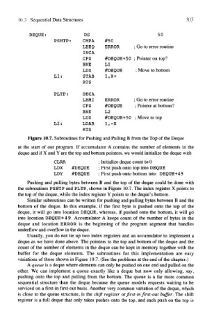
DEQUE: DS 50
PSHTP: CMP A #50
LBEQ ERROR ; Go to error routine
INC A
CPX #DEQUE+50 ; Pointer on top?
BNE LI
LDX #DEQUE ; Move to bottom
LI: STAB 1,X+
RTS
PLTP: DECA
LBMI ERROR ; Go to error routine
CPX #DEQUE ; Pointer at bottom?
BNE L2
LDX #DEQUE+50 ; Move to top
L2: LDAB 1, -X
RTS
Figure 10.7. Subroutines for Pushing and Pulling B from the Top of the Deque
at the start of our program. If accumulator A contains the number of elements in the
deque and if X and Y are the top and bottom pointers, we would initialize the deque with
CLRA ; Initialize deque count to 0
LDX #DEQUE ; First push onto top into DEQUE
LDY #DEQUE ; First push onto bottom into DEQUE+49
Pushing and pulling bytes between B and the top of the deque could be done with
the subroutines PSHTP and PLTP, shown in Figure 10.7. The index register X points to
the top of the deque, while the index register Y points to the deque's bottom.
Similar subroutines can be written for pushing and pulling bytes between B and the
bottom of the deque. In this example, if the first byte is pushed onto the top of the
deque, it will go into location DEQUE, whereas, if pushed onto the bottom, it will go
into location DEQUE+4 9. Accumulator A keeps count of the number of bytes in the
deque and location ERROR is the beginning of the program segment that handles
underflow and overflow in the deque.
Usually, you do not tie up two index registers and an accumulator to implement a
deque as we have done above. The pointers to the top and bottom of the deque and the
count of the number of elements in the deque can be kept in memory together with the
buffer for the deque elements. The subroutines for this implementation are easy
variations of those shown in Figure 10.7. (See the problems at the end of the chapter.)
A queue is a deque where elements can only be pushed on one end and pulled on the
other. We can implement a queue exactly like a deque but now only allowing, say,
pushing onto the top and pulling from the bottom. The queue is a far more common
sequential structure -than the deque because the queue models requests waiting to be
serviced on a first-in first-out basis. Another very common variation of the deque, which
is close to the queue structure, is the shift register or first-in first-out buffer. The shift
register is a full deque that only takes pushes onto the top, and each push on the top is