
Page 341 - Introduction to Microcontrollers Architecture, Programming, and Interfacing of The Motorola 68HC12
P. 341
318 Chapter!! Input/Output
Recall from Chapter 1 that a computer is divided into its major components; the
controller, data operator (arithmetic/logic unit), memory, and input-output unit (see
Figure 11.1). Input and output instructions use the same address and data bus as load and
store instructions with memory, but the action of input and output instructions on
input-output hardware is a bit different than the action of load and store instructions on
memory. In many microcontrollers, different instructions are used for memory reads or
writes than for input or output operations, even though essentially the same pins are
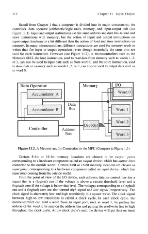
used for each instruction. However (see Figure 11.2), in microcontrollers such as the
Motorola 6812, the load instruction, used to read data from memory such as words 1,2,
or 3, can also be used to input data such as from word 0, and the store instruction, used
to store data in memory such as words 1,2, or 3, can also be used to output data such as
to word 0,
Figure 11.2. A Memory and Its Connection to the MPU (Compare to Figure 1.3)
Certain 8-bit or 16-bit memory locations are chosen to be output ports
corresponding to a hardware component called an output device, which has output lines
connected to the outside world. Certain 8-bit or 16-bit memory locations are chosen as
input ports, corresponding to a hardware component called an input device, which has
input lines coming from the outside world.
From the point of view of the I/O device, each address, data, or control line has a
signal that is a (logical) one if the voltage is above a certain threshold level and a
(logical) zero if the voltage is below that level. The voltages corresponding to a (logical)
one and a (logical) zero are also termed high signal and low signal, respectively. The
clock signal is alternately low and high repetitively in a square wave. The clock signal
between high-to-low transitions is called a clock cycle. In each clock cycle, the
microcontroller can read a word from an input port, such as word 3, by putting the
address of the word to be read on the address bus and putting the read/write line to high
throughout the clock cycle. At the clock cycle's end, the device will put data on input