
Page 346 - Introduction to Microcontrollers Architecture, Programming, and Interfacing of The Motorola 68HC12
P. 346
11.3 Input And Output Software 323
Note the ease of indexing a vector in a do while loop statement. This operation,
emptying data from a vector to an output port, is one of the most common of all I/O
programming techniques.
Conversely, to input a vector of bytes, this time largest indexed byte first, with data
on the input lines of the simple input device, execute the following C procedure:
char buffer[0x10];
void roain() { char i = 0x10;
DDRA = 0; do buffer[i - 1] = PORTA; while(—i);
}
An optimized assembly-language program segment for the body of this C procedure is
LDD #$10 ; Generate 0 in Accumulator A, $10 in Accumulator B
STAA $2 ; Put 0 in direction, to make it input
LDX #BUFFER-1 ; Set index register X to base of vector
LOOP: LDAA $0 ; Get a byte from the input port
STAA B, X ; Write it into the vector, top element first
DBNE B, LOOP ; For each element of the vector
From the two examples above, the reader should be convinced that inputting to or
outputting from a vector is a very simple operation in either C or assembly language.
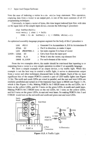
We show a simple example of an output device, a toy traffic light. While this
example is not the best way to control a traffic light, it serves to demonstrate output
from a vector and other techniques discussed later in the chapter. Each of the six least
significant bits of the output PORTA controls a pair of LED traffic lights (see Figure
11.5a). The north and south LEDs are wired in parallel, and the east and west LEDs are
similarly paralleled and turned on if the transistor base input is HIGH (see Figure 11.5b,
which is like Figure 11.4b). Making PORTA bit 5 HIGH turns on the red LEDs, bit 4
turns on the yellow LEDs, and bit 3 turns on the green LEDs, in north and south lanes.
Making PORTA bit 2 HIGH turns on the red LEDs, bit 1 turns on the yellow LEDs,
and bit 0 turns on the green LEDs, in east and west lanes. So making PORTA bits 5 and
0 HIGH would turn on the red north and south and green east and west LEDs.
Figure 115. A Traffic Light