
Page 351 - Introduction to Microcontrollers Architecture, Programming, and Interfacing of The Motorola 68HC12
P. 351
328 Chapter 11 Input/ Output
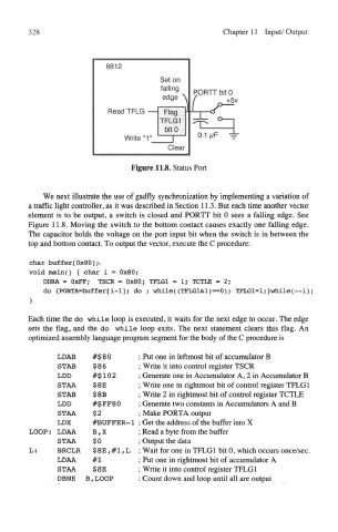
Figure 11.8. Status Port
We next illustrate the use of gadfly synchronization by implementing a variation of
a traffic light controller, as it was described in Section 113. But each time another vector
element is to be output, a switch is closed and PORTT bit 0 sees a falling edge. See
Figure 11.8. Moving the switch to the bottom contact causes exactly one falling edge.
The capacitor holds the voltage on the port input bit when the switch is in between the
top and bottom contact. To output the vector, execute the C procedure:
char buffer[0x80],v
void main() { char i = 0x80;
DDRA = OxFF; TSCR = 0x80; TFLG1 = 1; TCTLE = 2;
do <PORTA=buffer[i-l]; do ; while((TFLG1&1)==0); TFLGl=l;>while(—i);
}
Each time the do while loop is executed, it waits for the next edge to occur. The edge
sets the flag, and the do while loop exits. The next statement clears this flag. An
optimized assembly language program segment for the body of the C procedure is
LDAB #$80 ; Put one in leftmost bit of accumulator B
STAB $ 8 6 ; Write it into control register TSCR
LDD #$102 ; Generate one in Accumulator A, 2 in Accumulator B
STAA $ 8E ; Write one in rightmost bit of control register TFLG1
STAB $ 8B ; Write 2 in rightmost bit of control register TCTLE
LDD #$FF80 ; Generate two constants in Accumulators A and B
STAA $2 ; Make PORTA output
LDX #BUFFER-1 ; Get the address of the buffer into X
LOOP: LDAA B,X ; Read a byte from the buffer
STAA $0 ; Output the data
L: BRCLR $ 8 E, # 1, L ; Wait for one in TFLG 1 bit 0, which occurs once/sec.
LDAA #1 ; Put one in rightmost bit of accumulator A
STAA $8E ; Write it into control register TFLG1
DBNE B, LOOP ; Count down and loop until all are output