
Page 347 - Introduction to Microcontrollers Architecture, Programming, and Interfacing of The Motorola 68HC12
P. 347
324 Chapter 11 Input/ Output
We will output a vector of light patterns to the LEDs, largest indexed element first,
Because page-zero addressing is used for the STAA $0 instruction, a byte is output to
the LED display every eight clock cycles, which is every microsecond, much too fast for
any type of useful display. But an arbitrary delay can be easily added in the loop to
display each pattern as long as desired. To output an element every second, execute
char buffer[0x10];
void mairi() { char i = 0x10; long t;
DDRA=Oxff;do{PORTA=buffer[i-1];for(t=0;t<2666666;t++);}while(—i);
}
An optimized assembly language program segment for the body of this C procedure is
MOVE #$FF, $ 2 ; PORT A direction set for output
LDAB #$10 ; Vector Index initialized to high end
LDX #BUFFER-1 ; Base address of the vector
LOOP: LDAA B, X ; Get an element out of the vector
STAA $0 ; Write it into the output port
LDAA #100 ; Execute outer loop 100 times
WTO: LDY #80000/3 ; Execute the inner loop 26666 times
WT1: DBNE Y, WT1 ; Inner loop takes 10 ms
DBNE A, WTO ; Outer loop takes 1 second
DBNE B, LOOP ; Output all elements of the vector
The inner loop, the single instruction, WT1: DBNE Y, WT1, takes three memory
cycles. Because index register Y is initialized to 26666, this loop takes 80,000 memory
cycles, which, for an 8 MHz 6812 clock, takes 10 ms. The outer loop, including the
inner loop and LDY #80000/3 and DBNE A, WTO, is executed 100 times, delay ing
very close to 1 second. So the program segment outputs a vector element each second.
The vector buffer can therefore be initialized with appropriate bit pattern constants to
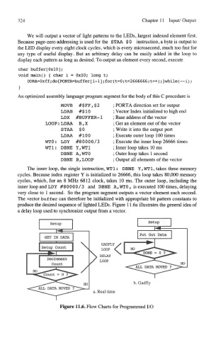
produce the desired sequence of lighted LEDs. Figure 11.6a illustrates the general idea of
a delay loop used to synchronize output from a vector.
Figure 11.6. Flow Charts for Programmed I/O