
Page 353 - Introduction to Microcontrollers Architecture, Programming, and Interfacing of The Motorola 68HC12
P. 353
330 Chapter 11 Input/ Output
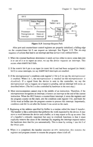
Figure 11.9. Interrupt Request Path
After port and counter/timer control registers are properly initialized, a falling edge
on the counter/timer bit 0 can request an interrupt. See Figure 11,9. The six-step
sequence of actions that lead to an interrupt and that service it are outlined below.
1. When the external hardware determines it needs service either to move some data into
it or out of it or to report an error, we say the device requests an interrupt. This
occurs when PORTT bit 0 falls.
2. If the PORTT bit 0 pin is an input (in DDRT bit 0) and had been assigned (in TMSK1
bit 0) to sense interrupts, we say PORTT bit 0 interrupts are enabled.
3. If the microprocessor's condition code register's I bit is 0 we say the microprocessor
is enabled. When I is 1, the microprocessor is masked (or the microprocessor is
disabled). If a signal from the device is sent to the controller, we say the
microprocessor sees a request, or a request is pending, and an interrupt will occur, as
described below. (The bit I is also controlled by hardware in the next step.)
4. Most microcomputers cannot stop in the middle of an instruction. Therefore, if the
microprocessor recognizes an interrupt, it honors an interrupt at the end of the current
instruction. When the 6812 honors a counter/timer interrupt, it saves the registers and
the program counter on the stack, sets the condition code register I bit, and loads the
16-bit word at Oxffee into the program counter to process this interrupt. Importantly,
condition code bit I is set after the former I was saved on the stack.
5. Beginning at the address specified by Oxffee is a routine called the timer 0 handler.
The handler is like a subroutine that performs the work requested by the device. It may
move a word between the device and a buffer, or it may report or fix up an error. One
of a handler's critically important but easy to overlook functions is that it must
explicitly remove the cause of the interrupt (by negating the interrupt request) unless
the hardware does that for you automatically. This is done by writing 1 into bit 0 of
the TFLG1 port.
6. When it is completed, the handler executes an RTI instruction; this restores the
registers and program counter to resume the program where it left off.