
Page 358 - Introduction to Microcontrollers Architecture, Programming, and Interfacing of The Motorola 68HC12
P. 358
1.1.7 Analog-to-Digital and Digital-to-Analog Conversion 335
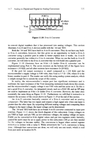
Figure 11.10. D-to-A Converter
to convert digital numbers that it has processed into analog voltages. This section
illustrates A-to-D and D-to-A devices usable with the 'A4 and 'B32.
Both the ' A4 and 'B32 have built-in A-to-D converters. They do not have any built-
in D-to-A converters, however, but this gives us an opportunity to build a D-to-A
converter using a parallel port in order to better explain how it works. An A-to-D
converter generally has within it a D-to-A converter. When we use the built-in A-to-D
converter, we will refer to the D-to-A converter that we will build into a parallel port.
Figure 11.10 illustrates how an 8-bit r-2r ladder D-to-A converter can be
implemented using Port A. The seven resistors on the bottom left of the figure have
resistance r (10 KQ), and all other resistors have resistance 2r (20 KQ).
If the port bit output resistance is small compared to r (10 KQ) and the
microcontroller's supply voltage is 5.00 volts, then Vout is 5 * D / 256, where D is the
binary number in port A. The reader can verify this using analog system analysis, which
is simple enough but is outside the scope of this course.
In reality, the microcontroller's output port has significant resistance and is
nonlinear; the input resistance of the Vout measuring instrument loads down this circuit,
and the microcontroller's supply voltage is not 5.00 volts and has noise on it. So this is
not a good D-to-A converter. An integrated circuit, such as a DAC-08, and an OP amp
are used to implement an 8-bit r-2r ladder D-to-A converter. However, the latter does
essentially the same thing as Figure 11.10. Furthermore we will find it instructive to
measure the accuracy of the circuit shown in Figure 11.10 at the end of this section.
An A-to-D converter basically consists of a D-to-A converter and an analog
comparator. The latter has two inputs and outputs a high signal only when one input is
greater than the other input. By outputting different analog voltages and comparing these
voltages to the input voltage, the input voltage can be determined.
The 'A4 and 'B32 both have an on-board A-to-D converter connected to input port
PORTAD. Figure 11.11 shows the block diagram of this subsystem. Using voltages on
pin VRH as high- and pin VRL as low-reference voltages, the analog voltage on inputs
PADO can be converted to 8-bit digital values and put into registers ADRO. Initially,
control bit ADPU must be set to apply power to this subsystem (100 /*s are then needed
for the voltages to become stable). The conversion is begun when control register
ATDCTL5 is written with a value 0. While ATDSTATO bit 7 is 0, conversion is being
done. Although four conversions are done, we will only use one result, which is read
from port ADRO at location 0x70.