
Page 359 - Introduction to Microcontrollers Architecture, Programming, and Interfacing of The Motorola 68HC12
P. 359
336 Chapter 11 Input/ Output
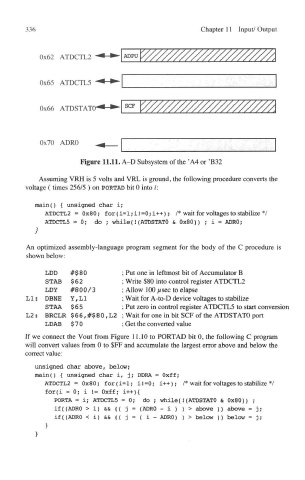
Figure 11.11. A-D Subsystem of the 'A4 or 'B32
Assuming VRH is 5 volts and VRL is ground, the following procedure converts the
voltage (times 256/5 ) on PORTAD bit 0 into i:
main() { unsigned char i;
ATDCTL2 = 0x80; for (i=l;iI=0; i++); /* wait for voltages to stabilize */
ATDCTL5 =0 ; do ; while(!(ATDSTATO & 0x80)) ; i = ADRQ;
}
An optimized assembly-language program segment for the body of the C procedure is
shown below:
LDD #$80 ; Put one in leftmost bit of Accumulator B
STAB $62 ; Write $80 into control register ATDCTL2
LDY #800/3 ; Allow 100 // sec to elapse
L1; DBNE Y, L1 ; Wait for A-to-D device voltages to stabilize
STAA $65 ; Put zero in control register ATDCTL5 to start conversi<
L2: BRCLR $66,#$80,L2 ; Wait for one in bit SCF of the ATDSTATO port
LDAB $ 7 0 ; Get the converted value
If we connect the Vout from Figure 11.10 to PORTAD bit 0, the following C program
will convert values from 0 to $FF and accumulate the largest error above and below the
correct value;
unsigned char above, below;
main() { unsigned char i, j; DDRA = Oxff;
ATDCTL2 = 0x80; for (i=l; i! =0; i++); /* wait for voltages to stabilize */
for(i =0 ; i != Oxff; i++){
PORTA = i; ATDCTL5 =0 ; do ; while(i(ATDSTATO & 0x80)) ;
if({ADRO > i) && (( j = (ADRO - i ) ) > above ) ) above = j;
if((ADRO < i) && (( j = ( i - ADRO) ) > below ) ) below = j;
>
}