
Page 360 - Introduction to Microcontrollers Architecture, Programming, and Interfacing of The Motorola 68HC12
P. 360
.1 ! .8 LI ART Protocol 337
Writing an optimized assembly-language program for this C procedure is left as an
exercise for the reader. But observe two aspects of this technique. The initialization of the
A-to-D device, which is required only before the first time you use the device, writes a
value in a device's control registers and waits 100//sec for voltages to stabilize. Each
time a conversion is needed, we write a value into the control register, wait in a gadfly
loop until conversion is completed, and read the value from the ADRO port,
We conducted an experiment that tied the output of Figure 11.10 to the AD port bit
0 input and ran the program shown above. The difference between the byte output from
PORT A and the value read from port ADRO was 4. Because the A-to-D converter is
well-designed, we assume the D-to-A converter had an accuracy of a little less than 1 %.
11.8 UART Protocol
The Universal Asynchronous Receiver-Transmitter (UART) is a module (integrated
circuit) that supports a frame protocol to send up to eight-bit frames (characters). We call
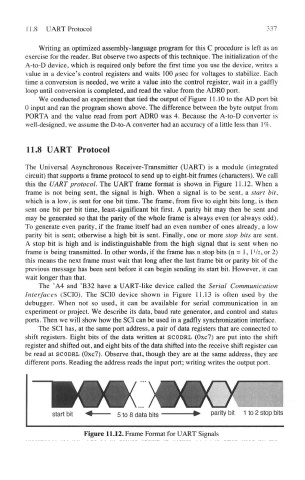
this the UART protocol. The UART frame format is shown in Figure 11.12. When a
frame is not being sent, the signal is high. When a signal is to be sent, a start bit,
which is a low, is sent for one bit time. The frame, from five to eight bits long, is then
sent one bit per bit time, least-significant bit first. A parity bit may then be sent and
may be generated so that the parity of the whole frame is always even (or always odd).
To generate even parity, if the frame itself had an even number of ones already, a low
parity bit is sent; otherwise a high bit is sent. Finally, one or more stop bits are sent.
A stop bit is high and is indistinguishable from the high signal that is sent when no
!
frame is being transmitted. In other words, if the frame has n stop bits (n = 1, 1 /2, or 2)
this means the next frame must wait that long after the last frame bit or parity bit of the
previous message has been sent before it can begin sending its start bit. However, it can
wait longer than that.
The 'A4 and 'B32 have a UART-like device called the Serial Communication
Interfaces (SCIO). The SCIO device shown in Figure 11.13 is often used by the
debugger. When not so used, it can be available for serial communication in an
experiment or project. We describe its data, baud rate generator, and control and status
ports. Then we will show how the SCI can be used in a gadfly synchronization interface.
The SCI has, at the same port address, a pair of data registers that are connected to
shift registers. Eight bits of the data written at SCO DHL (Oxc7) are put into the shift
register and shifted out, and eight bits of the data shifted into the receive shift register can
be read at SCODRL (Oxc7). Observe that, though they are at the same address, they are
different ports. Reading the address reads the input port; writing writes the output port.
Figure 11.12. Frame Format for UART Signals