
Page 365 - Introduction to Microcontrollers Architecture, Programming, and Interfacing of The Motorola 68HC12
P. 365
342 Chapter 11 Input/ Output
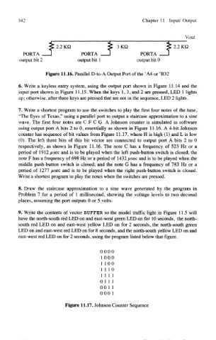
Figure 11.16. Parallel D-to-A Output Port of the 'A4 or 'B32
6. Write a keyless entry system, using the output port shown in Figure 11.14 and the
input port shown in Figure 11.15. When the keys 1,3, and 2 are pressed, LED 1 lights
up; otherwise, after three keys are pressed that are not in the sequence, LED 2 lights.
7. Write a shortest program to use the switches to play the first four notes of the tune,
"The Eyes of Texas," using a parallel port to output a staircase approximation to a sine
wave. The first four notes are C F C G. A Johnson counter is simulated in software
using output port A bits 2 to 0, essentially as shown in Figure 11.16. A 4-bit Johnson
counter has sequence of bit values from Figure 11.17, where H is high (1) and L is low
(0). The left three bits of this bit vector are connected to output port A bits 2 to 0
respectively, as shown in Figure 11.16. The note C has a frequency of 523 Hz or a
period of 1912 /<sec and is to be played when the left push-button switch is closed; the
note F has a frequency of 698 Hz or a period of 1432 #sec and is to be played when the
middle push-button switch is closed; and the note G has a frequency of 783 Hz or a
period of 1277 /<sec and is to be played when the right push-button switch is closed.
Write a shortest program to play the notes when the switches are pressed.
8. Draw the staircase approximation to a sine wave generated by the program in
Problem 7 for a period of 1 millisecond, showing the voltage levels to two decimal
places, assuming the port outputs 0 or 5 volts.
9. Write the contents of vector BUFFER so the model traffic light in Figure 11.5 will
have the north-south red LED on and east-west green LED on for 10 seconds, the north-
south red LED on and east-west yellow LED on for 2 seconds, the north-south green
LED on and east-west red LED on for 8 seconds, and the north-south yellow LED on and
east-west red LED on for 2 seconds, using the program listed below that figure.
0000
1000
1100
111 0
1 1 1 1
0 1 1 1
001 1
0001
Figure 11.17. Johnson Counter Sequence