
Page 364 - Introduction to Microcontrollers Architecture, Programming, and Interfacing of The Motorola 68HC12
P. 364
PROBLEM'S 341
PROBLEMS
1. The least significant bit of a port, as shown in Figure 11.4, is connected as input to a
push-button switch. The signal from the switch is high if the button is not pressed and
low if it is pressed. However, when it is pressed or released, it "bounces," that is, it
changes value rapidly from high to low to high to low . . . for about 10 milliseconds.
Write a program segment that will loop until the button is down for at least 5
milliseconds without the signal changing value. (This is called a debouncer.)
2. Draw a diagram similar to that shown in Figure 11.4 in which three switches,
normally open, are connected in parallel, such that PORT A bit 0 is normally high,
becoming low when any switch is closed. Comment on why the circuit in Figure 11.4
is better than this circuit for a security system. (Hint: Consider ways to thwart the
alarm.)
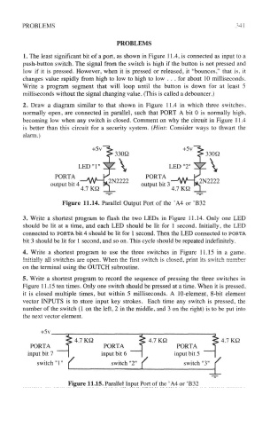
Figure 11.14. Parallel Output Port of the 'A4 or 'B32
3. Write a shortest program to flash the two LEDs in Figure 11.14. Only one LED
should be lit at a time, and each LED should be lit for 1 second. Initially, the LED
connected to PORTA bit 4 should be lit for 1 second. Then the LED connected to PORTA
bit 3 should be lit for 1 second, and so on. This cycle should be repeated indefinitely.
4. Write a shortest program to use the three switches in Figure 11.15 in a game.
Initially all switches are open. When the first switch is closed, print its switch number
on the terminal using the OUTCH subroutine.
5. Write a shortest program to record the sequence of pressing the three switches in
Figure 11.15 ten times. Only one switch should be pressed at a time. When it is pressed,
it is closed multiple times, but within 5 milliseconds. A 10-element, 8-bit element
vector INPUTS is to store input key strokes. Each time any switch is pressed, the
number of the switch (1 on the left, 2 in the middle, and 3 on the right) is to be put into
the next vector element.
Figure 11.15. Parallel Input Port of the ' A4 or 'B32