
Page 357 - Introduction to Microcontrollers Architecture, Programming, and Interfacing of The Motorola 68HC12
P. 357
334 Chapter 11 Input/ Output
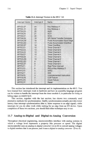
Table 11.1. Interrupt Vectors in the 6812 'A4
This section has introduced the interrupt and its implementation on the 6812. You
have learned how interrupts work in hardware and how an assembly-language program
can be written to handle the interrupt from the timer module 0, in particular for rising or
falling edges on PORTT bit 0.
This section, together with the last section, has shown two commonly used
alternative methods for synchronization. Gadfly synchronization actually provides lower
latency than interrupt synchronization (that is, faster response to an edge signal), while
interrupts let you do other work while waiting for an edge from an I/O device. Upon
completion of these two sections, you should find either technique easy to use.
11.7 Analog-to-Digital and Digital-to-Analog Conversion
Throughout electrical engineering, microcontrollers interface with analog systems in
which a voltage level represents a property like pressure or speed. The digital
microcontroller uses an analog-to-digital converter (A-to-D) to convert analog voltages
to digital numbers that it can process, and it uses a digital-to-analog converter (D-to-A)