
Page 54 - Introduction to Microcontrollers Architecture, Programming, and Interfacing of The Motorola 68HC12
P. 54
2.! Move Instructions 31
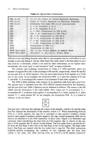
Table 23. Special Move Instructions
difficult to test and debug because some data in your program may be overwritten in your
attempt to test and debug it. On the other hand, this same stack is the best place to save
data used by a subroutine, which is not used by other subroutines, as we explain later.
Incidentally, the word "pop" is used instead of "pull" in many textbooks.
The transfer and exchange instructions in Table 2.3, TFR and EXG, allow the
transfer of register Rl to R2 or the exchange of Rl and R2, respectively, where Rl and R2
are any pair of 8- or 16-bit registers. You can move data from an 8-bit register to a 16-bit
one or vice versa. As an example, the instruction TFR D, Y puts the contents of D into
Y, and EXG D, X exchanged the contents of accumulator D and index register X.
The TFR or EXG machine code consists of an operation code byte and a post byte.
The opcode byte is obtained from the CPU12RG/D manual Instruction Set Summary,
and the post byte (see Table 3 therein) can be obtained as follows: The source is the left
nibble and the destination is the right nibble; their values are: 0, accumulator A; 1,
accumulator B; 2, condition code register; 4, accumulator D; 5, index register X; 6, index
register Y; 7, stack pointer SP. As an example, the instruction TFR D r Y is stored in
memory as the two bytes:
The post byte's left four bits indicate the source of the transfer, which is D, and the right
four bits indicate the destination of the transfer, which is Y. When transferring from an
8-bit to a 16-bit register, the sign bit is extended so that positive numbers remain
positive and negative numbers remain negative; the sign extend mnemonic SEX can be
used as an alternative to the TFR mnemonic in these cases. Figure 2.3a illustrates sign
extension when transferring the data from an 8-bit register, like A, shown on the top,
into a 16-bit register like X, shown on the bottom. The low-order byte is moved bit-by-
bit from the flip-flops in the 8-bit to the flip-flops in the 16-bit register. The high-order
byte's flip-flops are loaded with the low-order byte's sign bit. The EXG instruction
similarly permits exchanging the contents of two registers, and the post byte
coding is the same, but when moving from an 8-bit to a 16-bit register, instead of