
Page 57 - Introduction to Naval Architecture
P. 57
44 FLOTATION AND STABILITY
The changes in draught will be:
The new draughts become 5.751 m forward and 5.97m aft.
Hydrostatic curves
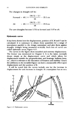
It has been shown how the displacement, position of B, M and F can be
calculated. It is customary to obtain these quantities for a range of
waterplanes parallel to the design waterplane and plot them against
draught, draught being measured vertically. Such sets of curves are
called hydrostatic curves, Figure 4.11.
The curves in the figure show moulded and extreme displacement.
The former was mentioned in Chapter 2. It is the latter, normally
shown simply as the displacement curve and which allows for
displacement outside the perpendiculars, and bossings, bulbous bows,
etc., which is relevant to the discussion of flotation and stability. Clearly
the additions to the moulded figure can have a measurable effect upon
displacement and the position of B.
It will be noted that the curves include one for the increase in
displacement for unit increase in draught. If a waterplane has an area
Figure 4.11 Hydrostatic curves