
Page 154 - Introduction to Petroleum Engineering
P. 154
ROTARY DRILLING RIGS 141
Crown block
Derrick
or
mast
“Fast line”
of hoisting Traveling block
cable Swivel
“Dead line”
of hoisting
cable
Draw works
Dead line anchor
Rotary table with
kelly bushing
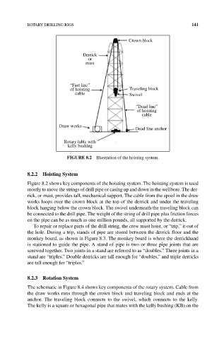
FIGuRe 8.2 Illustration of the hoisting system.
8.2.2 Hoisting System
Figure 8.2 shows key components of the hoisting system. The hoisting system is used
mostly to move the strings of drill pipe or casing up and down in the wellbore. The der-
rick, or mast, provides tall, mechanical support. The cable from the spool in the draw
works loops over the crown block at the top of the derrick and under the traveling
block hanging below the crown block. The swivel underneath the traveling block can
be connected to the drill pipe. The weight of the string of drill pipe plus friction forces
on the pipe can be as much as one million pounds, all supported by the derrick.
To repair or replace parts of the drill string, the crew must hoist, or “trip,” it out of
the hole. During a trip, stands of pipe are stored between the derrick floor and the
monkey board, as shown in Figure 8.3. The monkey board is where the derrickhand
is stationed to guide the pipe. A stand of pipe is two or three pipe joints that are
screwed together. Two joints in a stand are referred to as “doubles.” Three joints in a
stand are “triples.” Double derricks are tall enough for “doubles,” and triple derricks
are tall enough for “triples.”
8.2.3 Rotation System
The schematic in Figure 8.4 shows key components of the rotary system. Cable from
the draw works runs through the crown block and traveling block and ends at the
anchor. The traveling block connects to the swivel, which connects to the kelly.
The kelly is a square or hexagonal pipe that mates with the kelly bushing (KB) on the