
Page 169 - Introduction to Petroleum Engineering
P. 169
156 DRILLING
640 ac
5280ft
5280 ft
1 sq mi = 640ac
160 ac 2640ft 1320ft 40 ac
2640 ft 1320 ft
FIGuRe 8.11 Well spacing.
Horizontal from
slant hole
Side tracking from
vertical wells Stacked
Slant hole “S” curve laterals
Short
radius
Medium radius
Opposing laterals
“J” curve
Long radius
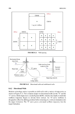
FIGuRe 8.12 Directional wells and multilateral wells.
8.4.2 Directional Wells
Modern technology makes it possible to drill wells with a variety of trajectories as
shown in Figure 8.12. Two common shapes for directional wells are the “S” and the
“J” curves. Both shapes have a kickoff point (KOP), which is the depth at which the
wellbore trajectory begins to deviate from vertical. An “S”‐curve wellbore is
designed to offset the drilling position before returning to a vertical orientation into
the target formation. The “J” curve gives a deviated wellbore trajectory into the
target formation.