
Page 57 - Introduction to Transfer Phenomena in PEM Fuel Cells
P. 57
46 Introduction to Transfer Phenomena in PEM Fuel Cells
Figure 1.20. Exploded view of a stacked PEM fuel cell
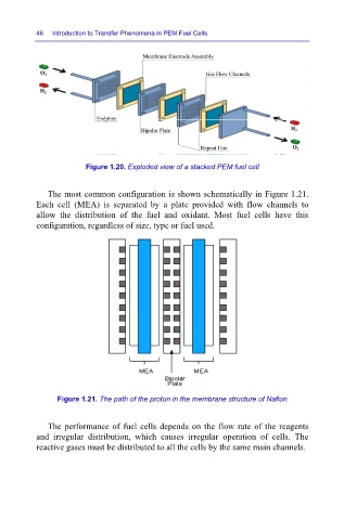
The most common configuration is shown schematically in Figure 1.21.
Each cell (MEA) is separated by a plate provided with flow channels to
allow the distribution of the fuel and oxidant. Most fuel cells have this
configuration, regardless of size, type or fuel used.
Figure 1.21. The path of the proton in the membrane structure of Nafion
The performance of fuel cells depends on the flow rate of the reagents
and irregular distribution, which causes irregular operation of cells. The
reactive gases must be distributed to all the cells by the same main channels.