
Page 142 - Know and Understand Centrifugal Pumps
P. 142
The System Curve
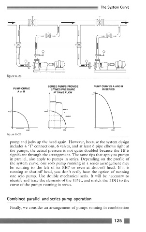
Figure 8-28
SERIES PUMPS PROVIDE PUMP CURVES A AND B
PUMP CURVE 2TlMES PRESSURE IN SERIES
A or 0 C, ATSAMEFLOW
1
H
FEET
Figure 8-29 GPM
~~~~ ~~~~ ~ ~ ~~ ~~~~ ~~~~ ~~~ ~ -~
pump and jacks up the head again. However, because the system design
includes 4 'T' connections, 6 valves, and at least 6 pipe elbows right at
the pumps, the actual pressure is not quite doubled because the Hf is
significant through the arrangement. The same tips that apply to pumps
in parallel, also apply to pumps in series. Depending on the profile of
the system curve, one solo pump running in a series arrangement may
be running to the left of its BEP or even at shut-off head. If it is
running at shut-off head, you don't really have the option of running
one solo pump. Use double mechanical seals. It will be necessary to
identifjr and trace the elements of the TDH, and match the TDH to the
curve of the pumps running in series.
Combined parallel and series pump operation
~~
Finally, we consider an arrangement of pumps running in combination