
Page 20 - Know and Understand Centrifugal Pumps
P. 20
Basic Pump Principles
-
ROTATION
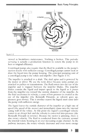
Fiaure 1-3
viewed as breakdown maintenance. Nothing is broken. This periodic
servicing is actually a production function to return the pump to its
best or original efficiency.
Centrifugal pumps also require that the fluid be available to the pump’s
suction nozzle with sufficient energy. Centrifugal pumps cannot suck or
draw the liquid into the pump housing. The principal pumping unit of
a centrifugal pump is the volute and impeller. (See Figure 1-3).
The impeller is attached to a shaft. The shaft spins and is powered by
the motor or driver. We use the term driver because some pumps are
attached to pulleys or transmissions. The fluid enters into the eye of the
impeller and is trapped between the impeller blades. The impeller
blades contain the liquid and impart speed to the liquid as it passes
from the impeller eye toward the outside diameter of the impeller. As
the fluid accelerates in velocity, a zone of low pressure is created in the
eye of the impeller (the Bernoulli Principle, as velocity goes up,
pressure goes down). This is another reason the liquid must enter into
the pump with sufficient energy.
The liquid leaves the outside diameter of the impeller at a high rate of
speed (the speed of the motor) and immediately slams into the internal
casing wall of the volute. At this point the liquid’s centrifugal velocity
comes to an abrupt halt and the velocity is converted into pressure (the
Bernoulli Principle in reverse). Because the motor is spinning, there is
also rotary velocity. The fluid is conducted from the cutwater around
the internal volute housing in an ever-increasing escape channel. As the
pathway increases, the rotary velocity decreases and even more energy