
Page 209 - Know and Understand Centrifugal Pumps
P. 209
Know and Understand Centrifugal Pumps
50% 50% of face contact
area sees closing
50% force.
Figure 13-14
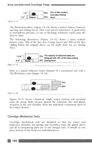
The illustration above (Figure 13-14) shows a perfect balance between
opening and closing forces. This is not always convenient. A quick drop
in atmospheric pressure, or loss of discharge resistance could cause the
faces to open.
The following illustration (Figure 13-1 5) shows a more realistic
balance ratio. 70% of the face sees closing forced and 30% of the face
(falling below the stepped sleeve on the shaft) does not see closing
force.
1.4 In2 70% The majority of balanced seals are
designed with 70% of the faces seeing
.61n2 {I Sleeve I 30% closing force.
Figure 13-15
Here is a typical balanced rotary element of a mechanical seal with a
70/30-balance ratio (Figure 13-16).
] 70%
3 30%
Fiaure 13-16
Figure 13-17 shows a balanced, single, rotary element seal mounted
onto the pump shaft, pressed against the stationary face and gland,
mounted in the seal chamber. Note the individual component parts of
the rotary element.
Ca rt r i dg e M ec h a n ica I Sea Is
Cartridge mechanical seals are designed so that the rotary and
stationary elements, the springs and secondary seals, the gland, sleeve
and all accompanying parts are in one integral unit. It installs in one
piece instead of the numerous individual pieces.
192