
Page 207 - Know and Understand Centrifugal Pumps
P. 207
Know and Understand Centrifugal Pumps
7. Compensates Operational Practices - It’s a common practice in
many plants to close or throttle a discharge valve with the pump
running to meter the flow through the pipes.
8. Pressure Spikes - They’re inherent in the design of many systems.
9. Eliminate the Re-circulation line - A discharge bypass line is
wasted energy and lost efficiency. Eliminate it with a balanced
seal.
10. Less external flush - Less heat generated signifies less cooling
requirements. Balanced seals can be flushed with as little as 1 or 2
gallons per hour.
11. No need to cool hot water - If the seal’s elastomer can take the
temperature, and the fluid is pressurized above its vapor pressure,
the cooling line can be eliminated.
Balance explained by math
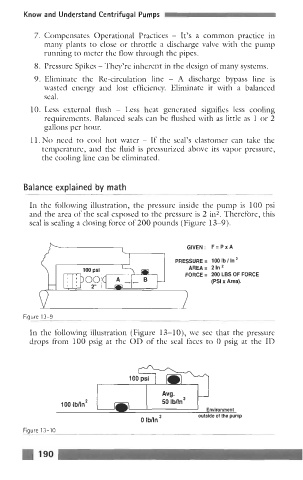
In the following illustration, the pressure inside the pump is 100 psi
and the area of the seal exposed to the pressure is 2 in2. Therefore, this
seal is sealing a closing force of 200 pounds (Figure 13-9).
GIVEN: F=PXA
PRESSURE= 1001b/In2
.
I ~
100 psi AREA= 21n2
FORCE = 200 LBS OF FORCE
B (PSI x Area).
Figure 13-9
In the following illustration (Figure 13-10), we see that the pressure
drops from 100 psig at the OD of the seal faces to 0 psig at the ID
100 lbnnZ
Environment
outside of the pump
o ibnn
Figure 13-10
190