Page 295 - LEGO MINDSTORMS - Robotics Invention System-2 Projects
P. 295

Robot 9 • The SpinnerBot
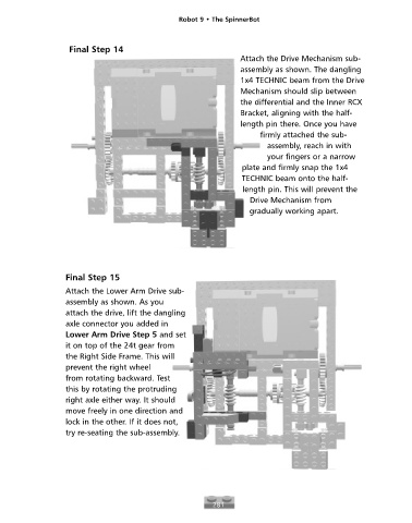


                        Final Step 14
                                                                        Attach the Drive Mechanism sub-
                                                                        assembly as shown. The dangling
                                                                        1x4 TECHNIC beam from the Drive
                                                                        Mechanism should slip between
                                                                        the differential and the Inner RCX
                                                                        Bracket, aligning with the half-
                                                                        length pin there. Once you have
                                                                             firmly attached the sub-
                                                                               assembly, reach in with
                                                                               your fingers or a narrow
                                                                        plate and firmly snap the 1x4
                                                                        TECHNIC beam onto the half-
                                                                        length pin. This will prevent the
                                                                          Drive Mechanism from
                                                                          gradually working apart.


                       Final Step 15
                       Attach the Lower Arm Drive sub-
                       assembly as shown. As you
                       attach the drive, lift the dangling
                       axle connector you added in
                       Lower Arm Drive Step 5 and set
                       it on top of the 24t gear from
                       the Right Side Frame. This will
                       prevent the right wheel
                       from rotating backward. Test
                       this by rotating the protruding
                       right axle either way. It should
                       move freely in one direction and
                       lock in the other. If it does not,
                       try re-seating the sub-assembly.


                                                                281
   290   291   292   293   294   295   296   297   298   299   300