
Page 221 -
P. 221
243_MasterPieces_04b.qxd 4/18/03 7:07 PM Page 193
PneumADDic II • Masterpiece 4 193
Pump sub-assembly or the pneumatic switch in the Dual Motor Switch sub-assembly.
The pneumatic switch is easier to activate compared to the pumps, but once the switch
has reached the switch lever limit, the switch lever will not move any more; therefore, at
that point the pumps in the Pump sub-assembly are easier to turn. Once the pneumatic
switch has been flipped all the power from the motors is applied to the pumps.
When the RCX wants to flip the switch, it applies power to the motors for a short
time in the direction needed to flip the switch. When the RCX wants to run the com-
pressor, without flipping the switch, it powers the motors in the same direction it used
last time it flipped the switch.The pumps are not affected by the gear direction that com-
press the pumps. Only the switch is affected by the direction the motors are turning.The
differential provides a wonderfully simple way to combine the switch and the pumps
using the single set of motors.
In the final assembly of PneumADDic II, we need to be able to see how to hook the
ports of the Dual Motor Switch assembly to the rest of the pneumatic circuitry for
PneumADDic II. If we add the entire compressor to the design at once, you cannot see
the Dual Motor Switch sub-assembly, making it difficult to discern how to connect it to
the rest of the circuit.To solve this building instruction problem, I’ve broken the com-
pressor up into the Dual Motor Switch sub-assembly, and Pumps sub-assembly, which I
add in two different steps in the final assembly.The following building instructions
describe how to build the Dual Motor Switch sub-assembly.
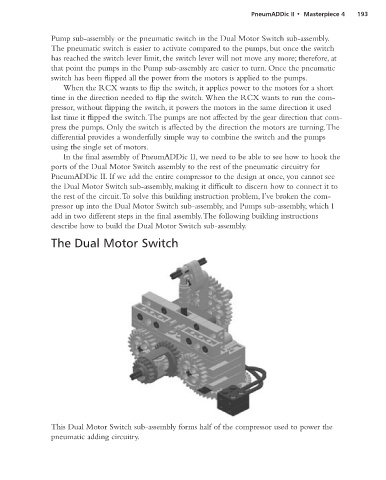
The Dual Motor Switch
This Dual Motor Switch sub-assembly forms half of the compressor used to power the
pneumatic adding circuitry.