
Page 246 -
P. 246
243_MasterPieces_04c.qxd 4/22/03 1:18 PM Page 218
218 Masterpiece 4 • PneumADDic II
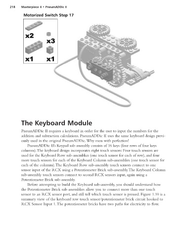
Motorized Switch Step 17
The Keyboard Module
PneumADDic II requires a keyboard in order for the user to input the numbers for the
addition and subtraction calculations. PneumADDic II uses the same keyboard design previ-
ously used in the original PneumADDic.Why mess with perfection!
PneumADDic II’s Keypad sub-assembly consists of 16 keys (four rows of four keys
columns).The keyboard design incorporates eight touch sensors: Four touch sensors are
used for the Keyboard Row sub-assemblies (one touch sensor for each of row), and four
more touch sensors for each of the Keyboard Column sub-assemblies (one touch sensor for
each of the columns).The Keyboard Row sub-assembly touch sensors connect to one
sensor input of the RCX using a Potentiometer Brick sub-assembly.The Keyboard Column
sub-assembly touch sensors connect to second RCX sensors input, again using a
Potentiometer Brick sub-assembly.
Before attempting to build the Keyboard sub-assembly, you should understand how
the Potentiometer Brick sub-assemblies allow you to connect more than one touch
sensor to an RCX sensor port, and still tell which touch sensor is pressed. Figure 1.10 is a
summary view of the keyboard row touch sensor/potentiometer brick circuit hooked to
RCX Sensor Input 1.The potentiometer bricks have two paths for electricity to flow.