Page 247 -
P. 247

243_MasterPieces_04c.qxd  4/22/03  1:18 PM  Page 219


                                                                               PneumADDic II • Masterpiece 4   219


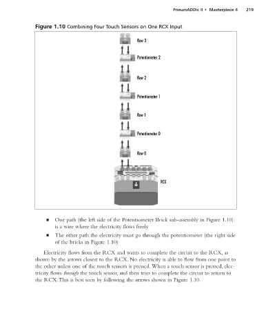
                    Figure 1.10 Combining Four Touch Sensors on One RCX Input


                                                                Row 3


                                                                Potentiometer 2


                                                                Row 2


                                                                Potentiometer 1


                                                                Row 1


                                                                Potentiometer 0


                                                                Row 0


                                                                          RCX


                         ■   One path (the left side of the Potentiometer Brick sub-assembly in Figure 1.10)
                             is a wire where the electricity flows freely

                         ■   The other path the electricity must go through the potentiometer (the right side
                             of the bricks in Figure 1.10)

                        Electricity flows from the RCX and wants to complete the circuit to the RCX, as
                    shown by the arrows closest to the RCX. No electricity is able to flow from one point to
                    the other unless one of the touch sensors is pressed. When a touch sensor is pressed, elec-
                    tricity flows through the touch sensor, and then tries to complete the circuit to return to
                    the RCX.This is best seen by following the arrows shown in Figure 1.10.
   242   243   244   245   246   247   248   249   250   251   252