Page 127 - MEMS Mechanical Sensors
P. 127

116                                                                 Pressure Sensors

                                                         2
                                                     2
                                                            1 2
                                F= PA 1             F = PA = FA/A 1
                                 1
                                                                          d2
                                          d1


                 Figure 6.4  Hydraulic force multiplication [1].


                 shown in (6.5), states that for an inviscid (zero viscosity), incompressible, steady
                 fluid flow of velocity v with negligible change in height, the static pressure (p) plus
                 dynamic pressure equals the total pressure (p ), which is a constant.
                                                         t
                                                ρ v 2
                                             p+     =  p t                             (6.5)
                                                 2

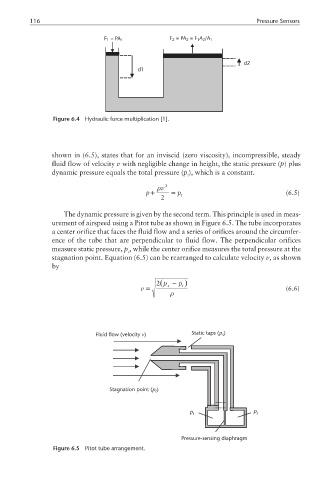
                    The dynamic pressure is given by the second term. This principle is used in meas-
                 urement of airspeed using a Pitot tube as shown in Figure 6.5. The tube incorporates
                 a center orifice that faces the fluid flow and a series of orifices around the circumfer-
                 ence of the tube that are perpendicular to fluid flow. The perpendicular orifices
                 measure static pressure, p , while the center orifice measures the total pressure at the
                                       s
                 stagnation point. Equation (6.5) can be rearranged to calculate velocity v, as shown
                 by

                                                2 (p −  p  )
                                           v =     s    t                              (6.6)
                                                    ρ


                                                                   p
                              Fluid flow (velocity )       Static taps ( ) s
                                            v


                                  Stagnation point ( )
                                               p
                                                t
                                                          p t                p s


                                                       Pressure-sensing diaphragm
                 Figure 6.5  Pitot tube arrangement.
   122   123   124   125   126   127   128   129   130   131   132