
Page 226 - MEMS and Microstructures in Aerospace Applications
P. 226
Osiander / MEMS and microstructures in Aerospace applications DK3181_c010 Final Proof page 217 1.9.2005 12:13pm
Microsystems in Spacecraft Guidance, Navigation, and Control 217
Other performance parameters such as angular rate sensing range and dynamic
bandwidth also are used to characterize and classify gyros. There are typically four
classes of gyros, in order of decreasing accuracy; precision (or strategic) class,
navigation class, tactical class, and consumer class. The overwhelming majority of
MEMS gyro R&D activities to date have been focused on gyros in either the tactical
performance class having bias stabilities in the range of 1 to 108/h or in the
consumer class where bias stability may be in the range of 100 to 10008/h or even
greater.
With the goal of developing navigation grade MEMS gyroscopes, DARPA has
invested in a number of programs, and has dramatically propelled MEMS inertial
sensor technology for DoD applications. Realizing its importance for space
applications, NASA, and especially JPL, has invested in the MEMS gyroscope
technology for space applications. 34,35
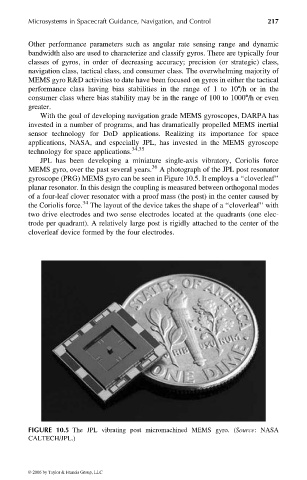
JPL has been developing a miniature single-axis vibratory, Coriolis force
MEMS gyro, over the past several years. 36 A photograph of the JPL post resonator
gyroscope (PRG) MEMS gyro can be seen in Figure 10.5. It employs a ‘‘cloverleaf’’
planar resonator. In this design the coupling is measured between orthogonal modes
of a four-leaf clover resonator with a proof mass (the post) in the center caused by
the Coriolis force. 34 The layout of the device takes the shape of a ‘‘cloverleaf’’ with
two drive electrodes and two sense electrodes located at the quadrants (one elec-
trode per quadrant). A relatively large post is rigidly attached to the center of the
cloverleaf device formed by the four electrodes.
FIGURE 10.5 The JPL vibrating post micromachined MEMS gyro. (Source: NASA
CALTECH/JPL.)
© 2006 by Taylor & Francis Group, LLC