
Page 243 - MEMS and Microstructures in Aerospace Applications
P. 243
Osiander / MEMS and microstructures in Aerospace applications DK3181_c011 Final Proof page 234 1.9.2005 12:31pm
234 MEMS and Microstructures in Aerospace Applications
11.2.1 PULSED PLASMA THRUSTER
Conventionally scaled pulsed plasma thrusters have been used in the past success-
fully and are fully space qualified. 9–16 Thrust is produced by ablating and acceler-
ating a solid insulator, such as Teflon, using a surface discharge initiated by high
voltage. Usually these systems are fairly massive ( 5 kg), but recent efforts have
been made to shrink the PPT for the use in micro- and nano-spacecraft. A micro-
pulsed plasma thruster (mPPT) has been developed by AFRL and Busek using
coaxial thruster configurations. A power conversion system converts the bus volt-
age to approximately 1 kV levels to ignite the discharge. Specific impulse (I sp )
values can reach up to 1000 sec, with mN-sec impulse bits.
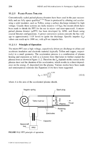
11.2.1.1 Principle of Operation
The micro-PPT uses a high voltage, capacitively driven arc discharge to ablate and
accelerate insulation and electrode material (typically Teflon and copper, respect-
ively) in a small geometry. The acceleration process is a combination of plasma
heating and expansion as well as a Lorentz force that helps to further expand the
plasma front as shown in Figure 11.2. Therefore the I sp depends on the current in the
plasma sheet and the duration of the acceleration, which results in a direct depend-
ence on the energy, E, deposited into the plasma. Various studies have been made
and semiempirical relations like Equation (11.6) have been suggested.
0:585
E
I sp ¼ 317 (11:6)
A
where A is the area of the accelerated plasma sheath.
Negator spring Spark plug
B
Teflon fuel bar
i Thrust
Plasma
Retaining
lid
Electrodes
Capacitor
Spacecraft
bus
PPU
FIGURE 11.2 PPT principle of operation.
© 2006 by Taylor & Francis Group, LLC