
Page 241 - MEMS and Microstructures in Aerospace Applications
P. 241
Osiander / MEMS and microstructures in Aerospace applications DK3181_c011 Final Proof page 232 1.9.2005 12:31pm
232 MEMS and Microstructures in Aerospace Applications
Ta
M PPU ¼ (11:3)
TTP
while the overhead mass for the chemical system remains fairly constant and is
assumed to be approximately 300 g.
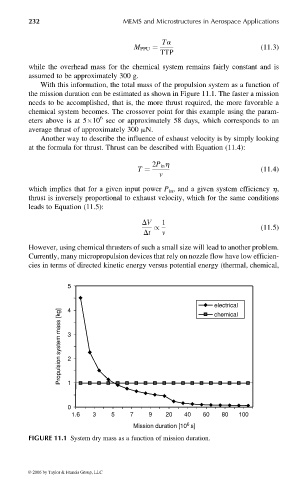
With this information, the total mass of the propulsion system as a function of
the mission duration can be estimated as shown in Figure 11.1. The faster a mission
needs to be accomplished, that is, the more thrust required, the more favorable a
chemical system becomes. The crossover point for this example using the param-
6
eters above is at 5 10 sec or approximately 58 days, which corresponds to an
average thrust of approximately 300 mN.
Another way to describe the influence of exhaust velocity is by simply looking
at the formula for thrust. Thrust can be described with Equation (11.4):
2P in h
T ¼ (11:4)
v
which implies that for a given input power P in , and a given system efficiency h,
thrust is inversely proportional to exhaust velocity, which for the same conditions
leads to Equation (11.5):
DV 1
/ (11:5)
Dt v
However, using chemical thrusters of such a small size will lead to another problem.
Currently, many micropropulsion devices that rely on nozzle flow have low efficien-
cies in terms of directed kinetic energy versus potential energy (thermal, chemical,
5
electrical
4
Propulsion system mass [kg] 3
chemical
2
1
0
1.6 3 5 7 9 20 40 60 80 100
6
Mission duration [10 s]
FIGURE 11.1 System dry mass as a function of mission duration.
© 2006 by Taylor & Francis Group, LLC