
Page 230 - Machinery Component Maintenance
P. 230
212 Machinery Component Maintenance and Repair
-LIPEARBox
VIEW
LOOKING
WEST
1 PAPPROX. V4"
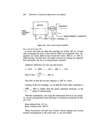
Figure 5-31. Motor close-coupled to gearbox.
(Text continued from page 205)
It can be seen that our final face readings are within .001 in. of each
other (although not zero) so this checks within our acceptable limit. Ap-
parently our motor shaft moved toward the motor .002 in. or -003 in.
while turning, but this does not matter because by having two opposite
face indicators, the error is automatically canceled.
Algebraic difference for face top and bottom:
(-.010) - (+.004) = -.010 - .004 = p.014
-.014 -
-
Half of this: - -.007 in.
2
This tells us that the top face distance is .007 in. wider.
Looking at the rim readings, we see that the motor shaft centerline is
-- - .003 in. higher than the pump centerline extension, at the
2 plane of measurement.
With this information, and using the dimensions shown in our sketch,
we use the plotting board and determine corrections as indicated in Fig-
ure 5-29:
Raise inboard feet .011 in.
Raise outboard feet .059 in.
These corrections will take care of both vertical angular and vertical
parallel misalignment at the same time, in one movement.