Page 226 - Machinery Component Maintenance
P. 226

208   Machinery  Component Maintenance and Repair

                                        SETUP  1A--TWO  INDICATOR
                                     FACE-AND-RIM  WITH STATIONARY
                                      SHAFT NOT  ROTATABLE BY  HAND


                                                         MACHINE IOENT IF I CATI;N+
                                                                       - -
                                                         LOCATION   #4 PWf  8  E
                                                         DATE
                                                         NAME  OF  ALIGNER    n. CARIG


                                                                               STATIONARY
                   TO BE  ADJUSTED                                             MRCHINE
                                                                               ELEMENT
                                                                                     €
                                                                           t         t
                                          THIS SHOULC BE
                   BASIC  DIMENSIONS      ”MEASUREMENT  DIAMETER.”         UP     DIRECTION
                                          WHICH MAY  OR  MAY  NOT
                                          EQUAL COUPLING HUE DIAMETER.


                         W
                           - ,015           LOOKING TOWARD MACHINE
                          +.obJ S4.G        ELEMENT  TO BE ADJUSTED.
                           - * 012  Mer
                     INTERPRETATION:
                               EXTENSION  of  machine to  be  adjusted IS:   006   W flower)  at  plane S.
                        V                         versus:         fhigherl flomrl  desired.
                        E             MACHINE  to  be  adjusted IS:   fhi@erl flomrl  at  plane A.
                        R
                        T                         versus:         (higher) flomr) desired.
                                              FACE  GAP  IS:   e  007   wider  at  the W fbortoml.
                     (TOP/BOTTOMl                 versus:         wider  at the  frwl lbortoml  desired.
                     ______________________________________________
                               EXTENSION  of  machine to  be  adjusted IS:   *  001   WE fW at  plane S.
                        H                         wrsus:          IN) IS) I€/ fW/  desired.
                        0
                         R            MACHINE  to  be  adjusted IS:   IN) IS) fE) fW/  at  plane A.
                         I                        wrws:           IN) fS/ I€)  fW1  denred.
                        z                     FACE  GAP  IS:   017   wider  at+m+swxw
                      lSlDE/SlOEl                 wrsus:          wider  at  IN) IS) (El fW/  desired.
                     CALCULATED CORRECTIVE  MOVES,  NOT CONSIDERING  OFFSETS:
                          %le/ feet         031   .  MOM inboard  feet   08L   IN)   fw).
                                  inboard
                          Hkial-l   outboard  feet   Ob2 ___ .  MOM  outboard  teat   170   IN) fS)E fm.
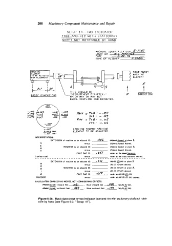
                       Figure 5-25.  Basic data sheet for two-indicator face-and-rim with stationary shaft not rotat-
                       able by hand (see Figure 5-3, “Setup 1A”).
   221   222   223   224   225   226   227   228   229   230   231