
Page 223 - Machinery Component Maintenance
P. 223
Machinery Alignment 205
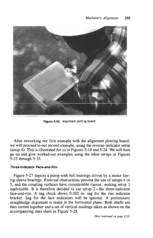
Figure 5-22. Alignment plotting board.
After reworking our first example with the alignment plotting board,
we will proceed to our second example, using the reverse-indicator setup
(setup 4). This is illustrated for us in Figures 5-18 and 5-24. We will then
go on and give worked-out examples using the other setups in Figures
5-25 through 5-33.
Three-Indicator Face-and-Rim
Figure 5-27 depicts a pump with ball bearings driven by a motor hav-
ing sleeve bearings. External obstructions prevent the use of setups 4 or
5, and the coupling surfaces have considerable runout, making setup 1
inadvisable. It is therefore decided to use setup 2-the three-indicator
face-and-rim. A sag check shows 0.002 in. sag for the rim indicator
bracket. Sag for the face indicators will be ignored. A preliminary
straightedge alignment is made in the horizontal plane. Both shafts are
then turned together and a set of vertical readings taken as shown on the
accompanying data sheet in Figure 5-28.
(Text continued on page 212)