
Page 220 - Machinery Component Maintenance
P. 220
202 Machinery Component Maintenance and Repair
(Text continued from page 199)
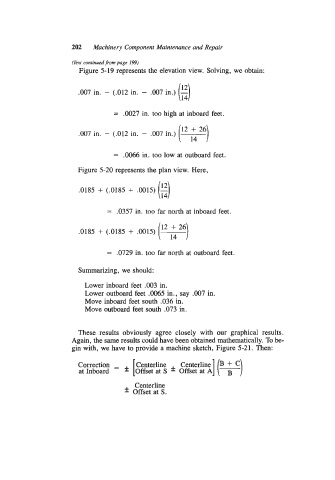
Figure 5-19 represents the elevation view. Solving, we obtain:
(3
.007 in. - (.012 in. - .007 in.) -
= .0027 in. too high at inboard feet.
.W7 in. - (.012 in. - .007 in.)
(” :4 26)
= .0066 in. too low at outboard feet.
Figure 5-20 represents the plan view. Here,
(3
.0185 + (.0185 + .0015) -
= .0357 in. too far north at inboard feet.
(12 L26)
.0185 + (.0185 + .0015)
= .0729 in. too far north at outboard feet.
Summarizing, we should:
Lower inboard feet .003 in.
Lower outboard feet .0065 in., say .007 in.
Move inboard feet south .036 in.
Move outboard feet south .073 in.
These results obviously agree closely with our graphical results.
Again, the same results could have been obtained mathematically. To be-
gin with, we have to provide a machine sketch, Figure 5-21. Then:
Correction = Centerline Centerline B + C
at Inboard * [Offset at S * Offset at A] (7)
Centerline
* Offset at S.