Page 216 - Machinery Component Maintenance
P. 216

198   Machinery  Component Maintenance and Repair

                        too far south, as are the feet. Therefore, net correction will be:

                         Move outboard feet .lo5 in. + ,017 in.  =  .122 in. north
                         Move inboard feet                        .017 in. north
                         It can be seen that our answers agree closely with those on the data
                        sheet, which were obtained graphically, The differences are not  large
                       enough to cause us trouble in the actual field alignment correction.
                         Alternatively, this first example could be solved with another similar
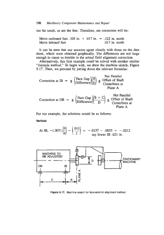
                        “formula method.” To begin with, we draw the machine sketch, Figure
                        5-17.  Then, we proceed by jotting down the relevant formulas:

                                                                  Net Parallel
                         Correction at IB  =                  f Offset of Shaft
                                                                 Centerlines at
                                                                    Plane A

                                                                       Net Parallel
                         Correction at OB  =
                                                                         Plane A

                        For our example, the solutions would be as follows:

                        Vertical
                         At IB,  -(.007)  (!)   - (F) - .0055  =  -.0212

                                                        -.0157
                                                     =
                                                          say lower IB .021 in.


                                                      1\1

                            MACHINE TO
                            BE ADJUSTED
                                                                             STATIONARY
                                                                             MACH  I NE


                                 Figure 5-17.  Machine sketch for  face-and-rim alignment method.
   211   212   213   214   215   216   217   218   219   220   221