
Page 304 - Machinery Component Maintenance
P. 304
286 Machinery Component Maintenance and Repair
To eliminate the need for physically biasing an arbor, balancing ma-
chine instrumentation can be furnished with a "double compensator."
This feature permits biasing of the machine indication by means of suit-
able electrical circuits.
The Double Compensator
As its name indicates, the double compensator has a two-fold purpose:
to eliminate errors in unbalance caused by tooling (thereby biasing the
tooling or arbor), and to compensate for initial workpiece unbalance dur-
ing machine setup.
Used in conjunction with 180" indexing, the compensator allows the
machine to indicate only the rotor's true unbalance. Typically, this works
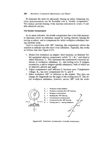
as follows (see also Figure 6-27).
1. Mount first workpiece on adapter. Start machine, on Schenck Tre-
bel equipment depress compensator switch "U + K1 ," and observe
initial indication, I1. This represents the combination (vectorial ad-
dition) of workpiece unbalance, U1, and tooling error E (adapter
eccentricity e and/or adapter-spindle unbalance) , both of which are
of unknown amount and angle.
2. Adjust compensator until indicator 1, becomes zero. Compensator
voltage, K1, has now compensated for U1 and E.
3. Index workpiece 180" in reference to the adapter. This does not
change the magnitude nor the angle of the tooling error E. The ini-
tial workpiece unbalance, however, moves 180" with the work-
I
U, = Workpiece initial unbalance
U2 = Workpiece unbalance after 180" indexing
II = Reading in initial position
K2
after
Reading
p
in
=
l2 K, = Compensation 180" initial indexing i t i o j
K2 = Compensation after 180" indexing UI -- I,
Ada kpirce
E = Tooling error (e + tooling unbalance)
KI -- 118
Ia
Figure 6-27. Schematic representation of double compensator.