
Page 308 - Machinery Component Maintenance
P. 308
290 Machinery Component Maintenance and Repair
be considered sufficient proof that the machine achieves a satisfactory
“Unbalance Reduction Ratio.” This, however, is only the case if the ini-
tial unbalance of the sample rotors is representative of the whole range of
initial unbalances that will be encountered in actual production parts.
Basic lest Concepts
From time to time over the last 30 or 40 years, the devising of proce-
dures for testing balancing machines, particularly dynamic balancing
machines, has occupied many experts and various committees of engi-
neering societies. The chief problem usually has been the interaction of
errors in amount indication, angle indication, and plane separation. A re-
quirement for a given accuracy of amount indication becomes meaning-
less if the machine’s indicating system has poor plane separation or lacks
accuracy of angle indication; or the best plane separation is useless if the
amount and angle indication are inaccurate.
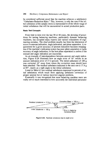
As an example of interdependence between amount and angle indica-
tion, Figure 6-28 illustrates how an angle error of 10” results in an
amount indication error of 17.4 percent. The initial unbalance of 100 g
was corrected 10” away from where the correction mass should have
been attached. The residual unbalance indicated in the next run is 17.4 g
at 85 O , nearly at a right angle to the initial unbalance.
Listed in Table 6-3 are residual unbalances expressed in percent of ini-
tial unbalances which result from applying unbalance correction of
proper amount but at various incorrect angular positions.
Eventually it was recognized that most balancing machine users are
really not so much interested in how accurately the individual parameter
Correction Mass = 100 g
Residual Unbalance = 17.4 g --
- / /-
/
Initial Unbalance = 100 g
Error in Applying
Correction Mass
Figure 6-28. Residual unbalance due to angle error.