
Page 311 - Machinery Component Maintenance
P. 311
Balancing of Machinery Components 293
be sufficient if the rotor fell within the bottom 20 percent of the ma-
chine weight range. For hard-bearing machines, it is not as important to
test the lower end of the weight range, since parasitic mass has little ef-
fect on the readout sensitivity of such machines.
Testing both soft- or hard-bearing machines in the upper 20 percent of
their weight range will verify their weight carrying and drive capability,
but add little additional knowledge concerning the measuring system. On
machines with weight ranges larger than 10,OOO lbs it may be impractical
to call for a test near the upper weight limit before shipment, since a bal-
ancing machine manufacturer rarely has such heavy rotors on hand. A
final test after installation with an actual rotor may then be the better
choice. In any case, it will generally suffice to include one small, or on
hard-bearing machines, one small to medium size proving rotor, in the
purchase of a machine. Rotors weighing several thousand pounds might
possibly be furnished temporarily by the balancing machine manufac-
turer for the acceptance test.
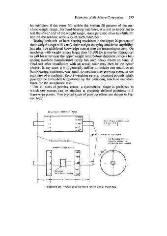
For all sizes of proving rotors, a symmetrical shape is preferred to
which test masses can be attached at precisely defined positions in 2
transverse planes. Two typical kinds of proving rotors are shown in Fig-
ure 6-29.
Solid Roll (ISO)-type Rotor
270.
0 300.
Test Plane Limitations:
0 330. brl; c=B
2 2
0 30'
Optional End-Drive Interface
I2 Threaded holes
Journal Center Lines equally spaced for
attaching test masses
Dumbbell-type Rotor
t-A~B--tc-i
Figure 6-29. Typical proving rotors for horizontal machines.