
Page 67 - Machinery Component Maintenance
P. 67
52 Machinery Component Maintenance and Repair
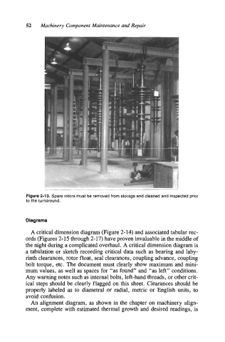
Figure 2-13. Spare rotors must be removed from storage and cleaned and inspected prior
to the turnaround.
Diagrams
A critical dimension diagram (Figure 2-14) and associated tabular rec-
ords (Figures 2-15 through 2-17) have proven invaluable in the middle of
the night during a complicated overhaul. A critical dimension diagram is
a tabulation or sketch recording critical data such as bearing and laby-
rinth clearances, rotor float, seal clearances, coupling advance, coupling
bolt torque, etc. The document must clearly show maximum and mini-
mum values, as well as spaces for “as found” and “as left” conditions.
Any warning notes such as internal bolts, left-hand threads, or other crit-
ical steps should be clearly flagged on this sheet. Clearances should be
properly labeled as to diametral or radial, metric or English units, to
avoid confusion.
An alignment diagram, as shown in the chapter on machinery align-
ment, complete with estimated thermal growth and desired readings, is