
Page 68 - Machinery Component Maintenance
P. 68
Maintenance Organization and Control for Multi-Plant Corporations 53
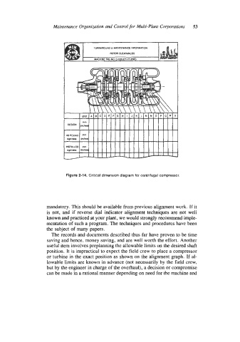
TURNAROUND a MAINTENANCE INFORMATION
ROTOR CLEARANCES
MACHINE TAG NO C-103 (ETHYLENE)
Figure 2-1 4. Critical dimension diagram for centrifugal compressor,
mandatory. This should be available from previous alignment work. If it
is not, and if reverse dial indicator alignment techniques are not well
known and practiced at your plant, we would strongly recommend imple-
mentation of such a program. The techniques and procedures have been
the subject of many papers.
The records and documents described thus far have proven to be time
saving and hence. money saving, and are well worth the effort. Another
useful item involves preplanning the allowable limits on the desired shaft
position. It is impractical to expect the field crew to place a compressor
or turbine in the exact position as shown on the alignment graph. If al-
lowable limits are known in advance (not necessarily by the field crew,
but by the engineer in charge of the overhaul), a decision or compromise
can be made in a rational manner depending on need for the machine and