
Page 64 - Make Your Own PCBs with EAGLE from Schematic Designs to Finished Boards
P. 64
resistor value.
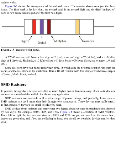
Figure 3-3 shows the arrangement of the colored bands. The resistor shown uses just the three
bands. The first band is the first digit, the second band is the second digit, and the third “multiplier”
band is how many zeros to put after the first two digits.
FIGURE 3-3 Resistor color bands.
A 270-Ω resistor will have a first digit of 2 (red), a second digit of 7 (violet), and a multiplier
digit of 1 (brown). Similarly, a 10-kΩ resistor will have bands of brown, black, and orange (1, 0, and
000).
Some resistors have four bands rather than three, in which case the first three stripes represent the
value, and the last stripe is the multiplier. Thus a 10-kΩ resistor with four stripes would have stripes
of brown, black, black, and red.
SMD Resistors
In general, through-hole devices are often of much higher power than necessary. Often ¼-W devices
are used as a standard that will do for almost any application.
SMD resistors are available with a wide range of power ratings, and generally, lower-power
SMD resistors are used rather than their through-hole counterparts. These devices start really small.
In fact, generally, they are too small to solder by hand.
SMD devices (both resistors and many other two-legged devices) come in standard sizes, denoted
by four digits, for example, 0402, 0805, and 1206. Figure 3-4 shows a selection of SMD resistors.
From left to right, the two resistor sizes are 0805 and 1206. As you can see from the match head,
theses are pretty tiny, and if you are soldering by hand, you should not consider devices smaller than
0805.