
Page 59 - Make Your Own PCBs with EAGLE from Schematic Designs to Finished Boards
P. 59
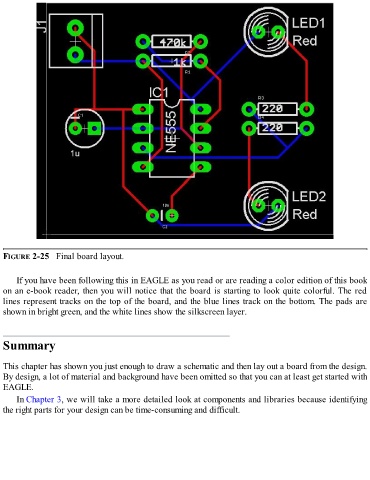
FIGURE 2-25   Final board layout.


      If you have been following this in EAGLE as you read or are reading a color edition of this book
  on an e-book reader, then you will notice that the board is starting to look quite colorful. The red
  lines represent tracks on the top of the board, and the blue lines track on the bottom. The pads are

  shown in bright green, and the white lines show the silkscreen layer.


  Summary


  This chapter has shown you just enough to draw a schematic and then lay out a board from the design.
  By design, a lot of material and background have been omitted so that you can at least get started with
  EAGLE.

      In Chapter 3, we will take a more detailed look at components and libraries because identifying
  the right parts for your design can be time-consuming and difficult.