
Page 134 - Making PIC Microcontroller Instruments and Controllers
P. 134
t24 CIOCKS. [Elf,OBY. Al{DSOCKETS
The emphasis in the pro$am we will develop is to see how we get the drla to and
from the real-time clock. Setting the clock is going to be done in the program sta{up
routine, and the time cannot be modified once the program is running lfyou want that'
you can add that to the program you write.
The DSl302 has 31 RAM registers. When you want to send or receive data to ihe
IC. the data can be transfeded to and frcm the clock/RAM one byte at a dme. or m a
bu$t oiup to 31 bytes.
The LTC1298 12-Bit A-to-D Converter
(Also Used in Socket U61
For our puposes, in making hstruments al1d confol lers, 8 , 10', and l2_bitA_to-D con
verters ar€ use.d as interfaces between sensors and microprocessors. Sensors usudly pro-
vide a change in rcsislance, inaluctance, or capacilance a.s some other factor is manipulated.
These changes are usually very small and need to be amplified and digitized so they cdn
be manipulated in a digital environment. The interiace that conve s these snall analog
signals to useful {tigital information is the A{o-D conve(er Getting comfofiable with
A-to-D conve(ers is an imponant pafi ol ma|ing instruments and controllers.
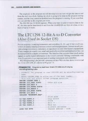
MicroEngineering Labs provide a program on their Web site that shows how to read
the l2-bit LTC1298. It's shown in Program 7.4.
Prosram to read lrom l2'bit LrCl298 A-to-D chip bv
:9!{E$!!;g$
microEnglneering
Labs
; PICBASIC PRO progran to read LTC1298 ADC by nicroEngineering
; Detuae LOADER USED to a11ow use of Lhe boo! loader.
; This witl not affect nomal pr:oqrm operallon.
DEFINE I.OADER_USED 1
DEFTNE I.CD-DREG PORTD i denne LU plns
DEFINE LCD_DBIT 4
DEFINE I-CD_RSREG PORTE
DEFTNE LCD_RSBIE O
DEFINE I.CD-EREG PORTE
DEFINE t|cD EBIT 1
IIICI,UDE'!{ODEDEFS. BA5"
CS VAR PORTI.s
cK vaR PoR