
Page 136 - Making PIC Microcontroller Instruments and Controllers
P. 136
126 clocKs. irE[oFY. AllD socKE s
Program 7.4 reads three values from the A to D converter and displays them as X
I. and Z values on the LCD. The 1298 is a two-channel device, and the two signals are
read from pins 2 and 3 on the device. The third value being displayed on the LCD is
the differential between the two values, meaning that the device is now being used fbr
lookng at the two inputs, not as individual inputs but as one signal aqoss the two lines
(as compa-red to two signals between each of the pins aIId $ound).
The two channels are cofirccted to the two pins at J5- These are ihe two pins that the
crystal for the clocks goes across and, as mentionedbeforc, because of this therc is a
hardwarc con|Ilct betuteen using the clock chip and the A-to-D con'erter.
The LtC 1298 can provide a m:L\imum of 11.1 thousand samples per second. The
device accepts an analog reference voltage between 0.3 and Vcc +0.3 volts, so the sig
nals to be read must be conditioned to rcflect these re4uirements.
U8)
Sockets U7 (and
Sockets U7 and U8 arc designed for temperature-sensing experiments. (U8 is a three-
hole group for soldering in a tbree wire temperature-sensing device and is located next
to U7.) How this is done is demonstrated in Programs 7.5 and 7.6.
The DSI820 tenperature rcading device goes i socket U7.
The DSI620 temperature sensor has to be sodered into socket U8.
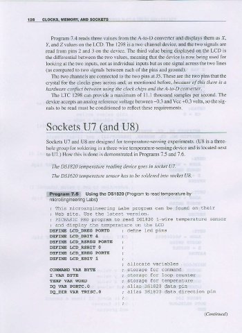
1?j&&!!!m5{{ Using the Dsl 820 (Program io read iemperature by
microEngineefing Labs)
; PICBASfC PRO proqrran to read DS1820 1 wire temperature sensot
^. Lhe LLD
DEFINE LCD DREG PORTD ; defne 1cd pins
DEFINE I.CD DEIIT 4
DEFINE I.CD RSREG PORTE
DEFINE I.CD RSEIT O
DEFINE ',CD EREG PORITE
DEFINE ',CD EAIT 1
allocaLe wariables
COMMAND VIR BYTA sLorage for comand
I VAR BYTE
fEMP VAR WORD
DQ Vt.R POR!C.o alias Ds1820 data pin
DLDIR VAR TRISC. O alias Ds1820 dala direction pin