
Page 174 - Making PIC Microcontroller Instruments and Controllers
P. 174
t6a cot{DllloNll{c THE l PUr SlGl{AL
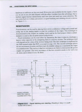
hardware or software as they arc read. If two pins are available for the signal' a latch
can be set at one pin and clearcd with the other' Lalches have the advantage that a
turclea "ignal ia;bes immediatcly altd then does not need any more attention- We
can comeiack to it when convenient. A signal latching and clearing circujt is shown
in Figure I l.l.
RES|StAilcEs
Potentiomcters be rcad by placing themacross a reference voltage and ground and
can
using one of the analog inputs 1o read the position of the wiper' This technique is
dem;nsrated in the chapter on rcading inputs and in the final project where a poten
tiometer is used as the set point determining device
Fixed resistances can be read either by measuring the time it takes to discharge a
known value capacitol or by comparing them to a known resistor' The technique used
js
will a"pend on ttre nat,re oithe resistor being read The iirst iechnique explained in
the PBi manual under the POT command on page 1 16 The second techniquc places
the two resistances in series and then reads the middle voltage as it represents the wtper
in a potentiometer. The caution is that low resistaoces are likely to shot across the powcr
supply and grounA. The total resistance of the two resislors needs to be well over
2k ohms and is bettcr if ovet 5k ohms.
5 V D D
A PUSHBUTTON
SWITCH ORTHE
DRY CONTACTS
10 hoHN,ls
SIGNALLATCHES
ONTO PIN 1 AND !S
CLEAFIEO WITH P]N 2
ittriiitt€rllr.lli sisnallatching and clearing. (Reading a relay or a prrEh-
bullon wiih a laich )