
Page 175 - Making PIC Microcontroller Instruments and Controllers
P. 175
ctRcutTRY FoR coltDtttoN tc Dc stcltlfs 169
Circui for Conditionin
24-VOLT SIGNALS
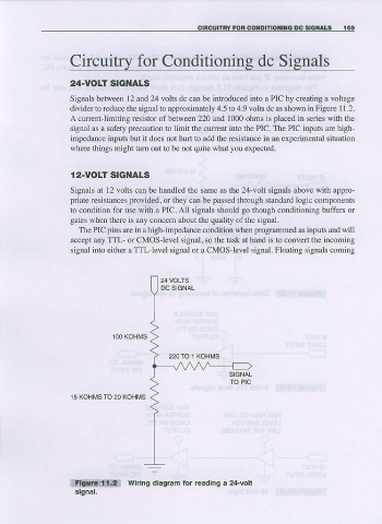
Signals between 12 and 24 volts dc can be introduced into a PIC by creating a voltage
divider to reduce the signal to approximately 4.5 to 4.9 volts dc as shown in Figure I L2.
A currentlimiting rcsistor of between 220 and 1000 ohms is placed in series with the
sigml as a safety precaution to limit the cuffent into the PIC. The PIC inputs are high
impedance inputs but it does not hul1 to add the rcsistance in an experimental situation
where things might tum out to be not quite what you expected.
r 2-voLT stcl{als
Signals at 12 volts can be handled the same as the 24-volt signals above with appro
priate resistances or ihey can be passed through standard logic components
Fovided,
to condition for use witlr a PIC. All signals should go though conditioning buffers or
gates wben there is any concern about the quality of the signal.
The PIC pins are in a high-impedance condition when programmed as inputs and will
accept any TTL or CMOS level signal, so the task at hand is to convert the incoming
signai ifto either a TTl-'level signal or a CMOS-level signal. Floating signals coming
100 KoHMS
15 KOHTVS TO 20 KOHNTS
l:tlli{di!:]t1a:: wiring diagram for readlng a 24-volt
stgnal,