
Page 193 - Making PIC Microcontroller Instruments and Controllers
P. 193
'I
PROJECT ta9
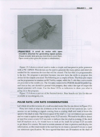
A small dc molor with open
encoders attached for generating signal pulses.
(Fewer encoder slots give you more time to couni them.
Open conslruclion
gives full access to electrcnics.)
Figure 15.3 shows a circuit used to make a simple and inexpensive pulse generator
with a PIC 16F819. This device can be used to generate the many pulses and intervals
needed for the numercus devices that will be created. The fact that it is programmable
is the key. No program is provided because you now have the skills to program this
device for the outputs you need. The following are acouple ofhi s. The tlree pin oupur
can be programmed to emulate an R/C hobby output, while the 5 volts that a se o needs
are provided at the middle pin. The five pins connected to PORTB should be pulled up,
and then as they arc shorted to ground with jumpers, they select the type of ouQut the
signal generator will create. Use the three LEDS as indicators to show you what is
goilg on in the progran
Figure 15.4 shows a picture of the nnished device. Bare boards and kits for ihis are
available at encodergeek.com.
PULSE RATE| LOW RATE COI{S|DEBAI|OI{S
Let's thini( about this iII terms of a small encoded motor like the one show! in Figure 15.2.
First, lefs look at what the problems at the low rpm end of the spectrum are. Let's
assume we are looking at signals coming from a rotating shaft and want to know the
speed of the shaft in rpm. The lowest speed of the shaft is 1 1p,t (revolutions per second)
and we want to update the rpm display every 0.25 seconds. We need to be able to detect
at least five counts every 0.25 seconds to indicate that the shaft is tuming.If the shaft
had 20 markers on it. we would have to look at the shaft for at least 0.25 secoDds
to get these five counts. We need a certain amount of time to prccess and display the
information. so the count needs to be read four to six times a second if we are to meet
our minimum specification. We have agreed that there are 20 markers on the shait of