
Page 198 - Making PIC Microcontroller Instruments and Controllers
P. 198
'I94 COUI{III{G PUISE$ A PROGRAIiIABIE TACHOflETER
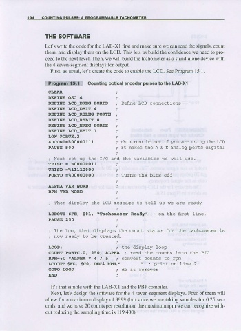
THE SOFIWARE
LeCs write the code for the LAB-XI first and make surc we can read the signals, count
them, and display them on the LCD. This lets us build the confidence we need to pro-
ceed to the next level. Then. we will build the tachometer as a stand-alone device with
the 4 seven segment displays for output.
First, as usual, Iet's create the code to enable the LCD. See Prc$am I5.1.
tl!,W*S*f{ counting optlcal encoder pulses to the LAB-X1
CI,EJAR
DEFINE OSC 4 j
DEFINE LCD_DREG PORTD ; De6ne LCD conneclions
DEFINE LCD.DBIT ' ;
DEFINE LCD_RSRTG PORTE ;
DEFINE LCD_RSBIT O ;
DEFINE LCD-EREC PORTE ;
DEFINE LCD_EBIT 1 ,
I,OW PORTE.2
aDCONI=%00000111 ; this nust be set if you are using the IrD
PAUSE 500 ; it mkes the A & E analog ports digital
. - r : _ \ 6 - _ - . i a b - s w a w j I I l s e .
e
TRISC - %00000011
TRISD .%11110000 ;
PORTD =%00000000 ; Turns lhe bits off
AjJPEA VAR WORD
RPM VAR WORD
; Then display lhe LcD nessage !o tell us we are ready
\Tachctrteter
LCDOIIT SFE, S01, Reaalyz ; on lhe frrst 1ine.
PAUSE 250
- f e ' o - - h -
; o o p . r , t o i s p d y s r " h o r e e r i
, now ready !o be crealed.
LOOP! ; the display loop
couNt PoREc.o. 250, ArPIra ; read lhe counls into lhe Prc
R I , ! d = 5 0 * a ! P I I A * 4 / 5 ; c o n v e r t c o u n l s ! o i p n
"
ICDOIIT SFE, 9C0, DECII RPM, \ ; print on line 2
GoIo I.ooP ; do it forever
END
It's that simple with the LAB-Xl and the PBPcompiler
Next,let's design the software for the 4 seven-segment displays. Four of them will
allow for a mfiimum display of 9q99 (but since we arc taking samples for 0.25 sec-
onds, and we have 20 counts per revolution, the ma,\imum lpm we can recognize with-
out reducing the sampling time is 119,400).