
Page 202 - Making PIC Microcontroller Instruments and Controllers
P. 202
IBLE TACHOMETEF
t98 COUllTlllG PULSES: A PFOGRAMT
Activate the fou(h conrmon line as you cycle tbrough the segments
Activate the seven segments one at a time
Go back to the beginning to do it again
There is one big difference between displaying on the LCD and displaying or the
seven-segment displays. Once you have written to the LCD, the information on the LCD
stays on the LCD. You do not have to do an,.thing else. However, on the seven segments
displays, the infomation must be updated conslantly. This means the driving routine
must be based on an anangement that is called often enough to make the display look
like it is on all the time.
The information you ne€d to lay out the wiring to implement the use of the 4 seven
segment displays is provided in Figures 15 9 to l5-11. Being able to look at the layout
from above and below makes it easier to visual the need of ihe top and bottom of the
PC board layout.
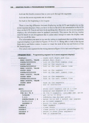
The actual code segment for the wiring shown in Figure 15.8 is laid out in hogfam 15.2
*!ilg.t*im$A! Programming segmenl for 4 seven-segmenl displays
DtSPI.AY: reads each disit and lhen
READ DIGITI. IIAIIT'E selecC f,rsL digit
PoRIA=%o0000001 lurn on the first cornnon tine
GOSUB SIIOW curn on ine segrenrs
PoRTA=%00000010 turn on the next comon Line
READ DIGITz, VIIIUE
GOSttB SBOW lurn on ane segmen!
PORTA-%00001000 lurn on the next comon line
RIAD Dr6rr3, VlttitE
GOSUB SHOIT turn on the segnents
PORTA-%o0100000 lurn on the next comon line
REA.D DIGIT4I V}ITUE
GOSttB SEOW turn on tne segrenrs
RETI'RII end of subroutine
SHOW! shous each segment one ar a tine
Z=811111110 selecls one segnent a! a Llne
FOR X=1 TO I do the I sesrenLs, includes dec. poinl
get walue co show
inhibils the decinaf point
POREB=VAI,uE I Z makes value and z setec! one segfienE
z = ( z < < L , + t go ro nexr se€E(enL
PAUSEUS P pause to snow seg enr
NEJKT X
F ^ n r A l r e n r ^ r - s F i n o
PAUSSUS P pause to show clear segnents
RETI'RN end of subroutine